Haemobile - in vitro blood flow model
To assess hemocompatibility, blood flow models are often used and can either consist of in vivo animal models or in vitro blood flow models. Given the disadvantages of animal models, such as higher costs, more variability, more time consuming, and insensitivity due to overwhelming short-term effects of tissue injury, in vitro blood flow models are more attractive. We have developed our own in vitro blood flow model (1) which offers several important advantages:
- Use of fresh human blood (within 30 minutes after blood withdrawal).
Pulsatile flow with physiological (wall) shear stress.- The model has a low background for thrombosis.
- Low concentration of anticoagulatns, typically 1.5 IU/mL Heparin.
- No blood-air interaction (as is the case in the Chandler model).
Another big advantage is the limited blood volume necessary per test loop, typically 3-5 mL. This enables the use of paired test samples, i.e., using blood from the same donor for test and control samples. This, in turn, minimizes the variance between donors, increasing contrast between hemocompatible and -incompatible materials and thus increasing the reliability of hemocompatibility testing.
Principle
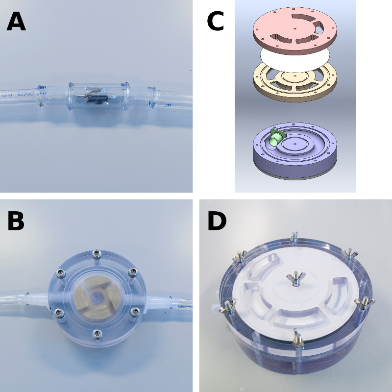
The principal of generating pulsatile flow inside a test loop is based on angular momentum. Blood inside a polyvinyl chloride test loop containing a unidirectional check valve (Fig. 1b) is exposed to an angular acceleration. The check valve functions as a heart valve, i.e., preventing backward flow of blood, and is also necessary to accelerate the blood as well as the test loop. Following acceleration, the test loop is decelerated again till a standstill. The angular momentum of the blood results in blood flowing relatively to the polyvinyl chloride test loop and is not hindered by the valve but only by shear forces. During this period of blood flow, the test loop is returned to its starting position. By repeating the process, a pulsatile flow is created. The video below clearly illustrates the generated flow inside a test loop.

Flow and (wall) shear stress
The main innovations of our model are pulsatile flow and controlled (wall) shear stress. We have characterized the hemodynamics of our model by performing Doppler flow measurements and calculating the corresponding velocity profiles and (wall) shear stress profiles (Fig. 2). By controlling the settings of the Haemobile, the desired velocity and (wall) shear stress profile can be created. In Fig. 2D the flow of a coronary artery is simulated.

Custom test chambers
Of course not every medical device fits easily inside a test loop. To test devices with more complicated geometries, we can design custom test chambers so that the Haemobile can still be used for hemocompatibility testing. Figure 3 shows several examples of custom designed test chambers.

If you would like to make use of our services or you would like to use the Haemobile at your own facility, please contact us.
